|
|
|
N0. 5. Aluminum Pillar Bedding for a more accurate rifle.
Remember Ernie's Rule:
For the least amount of stress in
your action.
Build your actions foundation
while using the least amount of force!
Do the 'Two Step"
Do the Bed Heads "Two
Step" pillar bedding process, that is.
While holding a pair of aluminum pillars in your hand, and contemplating "just what will these things do"?
You will recognize their ability to resist compression by pressure from the trigger guard screws. It is also apparent
that these pillars will space your rifles action and trigger guard a particular distance apart.
These are
Two Advantages, but with the "Bed Heads" Aluminum Pillar Bedding Kit, and the "Two Step" installation
process, you can have a Third, very important advantage. Whether you receive this advantage or not, depends on How
Your Pillars Are Installed. If you complete your pillar bedding job in just one step, (by bedding both the action
and the pillars simultaneously, with just one application of epoxy), the exact location of your pillars within the stock
will be determined while Hundreds of Pounds of pressure are being applied to the receiver by the trigger guard
screws. Your receiver will not have the strength to resist this pressure. The receiver will bend over
the top of any High Spots existing in the bedding surface, These High Spots will then
be duplicated in your finished bedding job. This bend, and this stress,will be captured in epoxy, and once again
Transferred Back to your Receiver, when the trigger guard screws are tightened for the final time.
Or,
you can achieve that Third Advantage, by installing the pillars in a Separate First Step, while using only a
Few Ounces of pressure.
Accomplish this First Step while the receiver is under No Stress
and the pillars are in Perfect Alignment with the receiver. Epoxy only the pillars into place in
the stock while they are attached to the receiver by the trigger guard screws, and the receiver is held
Lightly in place by rubber surgical tubing. Once the epoxy holding the pillars in the stock has hardened,
these pillars will provide a Solid Foundation. This foundation will support your receiver without pressure from
any other spot in the bedding surface. After removing the barreled action from the stock, you can be certain that this
is true, simply by scraping away all the rest of the bedding surface! Scrape as deep, or as shallow as you like.
Just be sure that when you are done scraping, your barreled action Touches nothing but the tops of the two pillars.
You do not have to be neat when you scrape this surface, you are just creating space between the stock and the receiver,
with the tops of the pillars left Standing Above the surrounding bedding surface in the stock.
Do the Second Step of this process by coating this scraped bedding surface with enough epoxy to replace the wood that
you have scraped away. Place your barreled action into this fresh bed of epoxy. Now, you will be free to use the
trigger guard screws to pull the receiver into place against its Already Solid Pillar Foundation. At the
same time, the remainder of the receiver will be establishing its own resting spot in a bed of soft epoxy. Remember
Ernie's rule, "For the least amount of stress in your action, install your actions foundation while using the least amount
of force!"
This "Two Step" installation process is designed specifically to deal
with the action flexibility described in Gunsmithing Odds and Ends #1.
| Picture #1 | 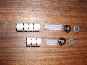 |
Here
are the contents of the "Bed Heads" Aluminum Pillar Bedding Kit. On the left, are the front
and the rear pillars. These pillars are 1/2" outside diameter, X 5/16" (.312") inside diameter.
Next are the Teflon sleeves, these sleeves are .312" OD X .250" ID. These sleeves play an important
role in the bedding process, as they center each pillar on its guard screw. The next 2 parts in line are the black
plastic spacers, and the steel spacer/washers. These 2 parts provide a means by which your actions trigger guard
screws can be used to tightly and accurately locate these pillars against the receiver, but without placing pressure on the
receiver in a way that would cause it to bend. (scroll down to picture #15. below). These two parts are used only
while completing the first step of the "2 Step" pillar bedding process. After the pillars have been epoxied
into the stock, (step one) the barreled action will be removed from the stock by removing the guard screws. Also remove
the steel washers and the black plastic spacers from the lower end of the pillars. These two parts will not be reused. However,
the Teflon sleeves will be left within the pillars during the remainder of the bedding job. This is done to prevent
leakage of epoxy into the I.D. of the pillars while the second application of epoxy is being completed.
| Picture #2 | 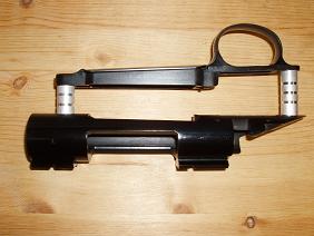 |
"Bed Heads" Pillars in a Remington M-700 BDL
These pillars fit all M-700 BDL rifles
with a factory hinged floorplate, and are in a factory wood stock.
These pillars also fit all M-700 BDL rifles
with factory hinged floorplate, and that are being installed in an aftermarket fiberglass/composite stock such
as a High-Tech, McMillan, or others.
| Picture #3 | 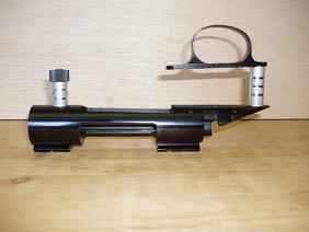 |
This Kit can also be used in factory Remington ADL stocks by shortening the front BDL pillar. The rear pillars are identical
in both ADL and BDL.
After reading through these instructions for the M-700 BDL, a supplemental guide
specific to the ADL will be Available
| Picture
#4 |  |
"Bed Heads" aluminum pillars are contoured on both ends to achieve form fitting, solid
contact with both the receiver and the trigger guard.
One end of each pillar
has a radius to match the radius of the receiver. The opposite end of the rear pillar is machined on an angle to match
the trigger guard.
Picture #4 illustrates the trigger guard while being supported only by the angled
end of the rear pillar. Notice how this angle supports the under side of the trigger guard assembly parallel to
the receiver, just as it needs to be when the rifle is fully assembled.
Bed Heads not only support
the receiver without stress, they even support the trigger guard without stress!
I know of no other
pillars being sold today that can make this claim. The right length, and with the right contour on both ends!
| Picture #5 |  |
How can the same length "Bed Heads" aluminum pillars fit all Remington M-700 BDL rifles, both short action,
and long action? One reason is in the trigger guard.
The front of the short action trigger
guard (on the left, in picture #5) is thicker and the front guard screw is longer, but the magazine box for both action lengths
is the same depth. Therefore, the pillar is the same length!
| Picture #6 |  |
Fortunately, for all of us wanting to install pillars in a Remington M-700
BDL, the magazine box depth has remained the same over the years.
On the left, is a .221 Remington
Fireball magazine box, which is the smallest centerfire cartridge Remington has chambered the M-700 for.
On the right, is a 300 Remington Ultra magazine box, one in a family of calibers which share the largest capacity cases offered
by Remington in the M-700.
Short action, or long action, big caliber, or small, they are all the
same depth, as you can see in picture #6. This gives us a standard to work to.
| Picture #7 |  |
Verify that pillars fit the action, (not the stock), and do this before they are trapped
in epoxy. As I said, the pillars must fit the action, and for the Remington M-700
BDL, fitting pillars to the action, really means fitting pillars to the magazine box.
When your rifle is assembled and ready to fire, the magazine box must remain free to "float" between the receiver
and the trigger guard as shown by the arrows in photo #7 The amount of this magazine box
clearance is determined by the length of the pillars, and since all the Remington M-700 BDL magazine boxes are the same depth,
all of the pillars for these guns can be the same length. It's just as simple as that!
"Bed Heads" pillars are sized to duplicate the average factory magazine box clearance of .030" to .040".
This is why "Bed Heads" pillars also fit most factory Remington M-700 BDL stocks.
A little later on in this process, you will verify that the stock fits the pillars, it usually will, but if a small adjustment
is necessary, you will make that adjustment to the stock and not to the pillars. (as in picture # 14)
One caution, concerning the adjustable length pillars available elsewhere, adjustable pillars can offer a very easy path
to the wrong conclusion. By that I mean, it is just so easy to adjust the pillar to a length which only fits the stock,
rather than to a length based on the reliable functioning of the action. Items such as
feeding from the magazine, reliable operation of both the safety and the trigger and of course, accuracy of the rifle itself,
can all be affected by relatively small variations in pillar length. Adjustable may sound
easy, but there is nothing easier than having pillars which are the right length and the right contour on both ends to
begin with. Do you have a fiberglass stock, or a semi inlet wood stock, and would like
to know exactly how much deeper the inletting needs to go? "Bed Heads" will provide the answer.
Do you have any kind of stock where the inletting is already too deep? "Bed Heads" will take the guesswork
out of repairing this problem.
| Picture #8 |  |
Once the holes for the pillars have been drilled, as described in Gunsmithing
Project #4, the next work necessary on the stock will be to float the barrel.
Begin this process
by removing the bedding pad shown in picture #8. Coarse sandpaper wrapped around a piece of wooden dowel is one way to do
this.
| Picture #9 |  |
Be sure that enough wood has been removed from this bedding pad area that the barrel
with 5 wraps of tape on it will fit, and still have a little bit of clearance between the tape and the forearm.
| Picture #10 |  |
You need enough tape to hold the barrel close to center in the barrel channel while the epoxy is
curing around the newly installed pillars. But not so much tape that it actually touches the barrel channel.
Since you do not want the tape to touch, the best you can do at this time is to hold the barrel somewhere near center.
After the completion of the bedding process, you may wish to go back and sand a small amount of material out of the barrel
channel as necessary to even the space on both sides of the barrel.
| Picture #11 |  |
Now we return to the holes drilled by the "pillar Align" cutter back
in Gunsmithing Project #4.
I like to add a little "texture" to these holes by running a 9/16 X
12 tap through them. You can do just as well with a moto-tool and a small burr. Just "rough up"
the surface in any way that will create a "mechanical lock" for the epoxy.
| Picture #12 | 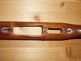 |
Back in picture #7, we
made sure that the pillars fit the magazine box. this means that the pillars are long enough to allow the magazine box
about .030" up and down movement between the receiver and the trigger guard. Now, it is time to be sure that the
stock fits the pillars. A good fit is described as being when the radius-ed end of the pillar is in solid contact with
the bottom of the receiver, and the other end of the pillar (that we see here in picture #12) is flush with the surrounding
wood, or slightly above it. If the pillar were rotated out of alignment with the receiver at this time,
the pillar would appear to be too long. To prevent this possibility, I suggest that the pillars be marked with a felt
tip pen as shown here. These marks will help to verify whether or not the pillars are properly oriented relative to the receiver.
I show 2 marks on the front pillar to suggest that it can be turned either one of two directions and still be correct.
One mark on the rear pillar indicates that there is only one correct direction for this rear pillar to face.
The center punch mark on the side of the pillar must face forward in order that the trigger guard be supported on the proper
angle (as in picture #4).
| Picture #13 | 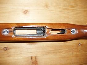 |
When you are certain that both pillars are in solid contact with the receiver, and are facing in the correct direction, you
can determine if any work will be necessary to fit the stock to the pillars.
In this particular rifle,
the front pillar was exactly flush with the surrounding wood.
However, the end of the rear pillar was .015"
below the surface of the surrounding wood.
| Picture
#14 | 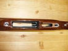 |
If either, or both, pillars are below the surface of the wood , it will only be necessary to scrape
a small amount of wood from the bottom of the trigger guard inletting. The wood surface needs to be flush with, or slightly
below the end of the pillar.
The light colored area surrounding the rear pillar provides an example of where
this wood needs to be removed.
| Picture #15 |  |
After removing the trigger, fill the trigger slot, the bolt stop slot, & the trigger pin holes with modeling clay.
Also add a layer of masking tape to the bottom of the recoil lug, but leave all 4 sides of the recoil lug tightly bedded
(no tape). With a round receiver, the largest surface available to resist rotation is the side of this lug.
Now, it is time to apply some type of mold release.
For the best fit, use the release agent
which creates the thinnest build-up on the surface of the metal. Johnson's paste wax is my favorite. Apply
with a brush, a cleaning patch, or a Q-Tip. After allowing this wax to dry for a few minutes, buff it off with a soft
cloth, just like you would wax your car.
For a little extra peace of mind, I go through
this wax and buff sequence twice. Cover every surface where epoxy, in your wildest dreams, could possibly
go.
| Picture
#16 |  |
Here we see a "Bed Heads" Aluminum Pillar Bedding Kit, attached to the receiver by its
trigger guard screws.
For the third time, be certain that the center punch mark on the rear pillar is facing
forward (toward the muzzle of the gun).
In addition to the existing grooves in the pillars, I use a small
die-grinder to add a random pattern of "notches" in the sides of both pillars. This provides the epoxy with
a stronger means of mechanically locking the pillars in place.
Use a Q-Tip to wax the interior, and
both ends, of each pillar. Wax the two steel washers supplied in the kit. Wax the entire surface of both screws,
including the under side of the screw heads. Do NOT wax the outer pillar surface visible in picture #16
There are three other things that I am trying to illustrate in this picture.
#1. The pillars
are in perfect alignment with the receiver, because they are being held in place by the trigger guard screws.
#2.
The pillars are concentric with the trigger guard screws, because they are being held on center by the teflon sleeves.
#3. This perfect alignment is being accomplished while the receiver is under no stress.
How do we maintain all three of the above conditions while planting those pillars in a bed of epoxy?
Achieving the first two conditions shown in picture #16. is easy, we just leave the pillars attached to
the receiver during the bedding process.
It is in the 3rd requirement of a stress free receiver, where
this installation process differs from others.
Rather than trying to bed everything at once, or even
doing the receiver and pillars at once, I believe that the pillars should be epoxied in place by themselves as a separate
first step. The less epoxy involved, the less pressure on the receiver. Once the epoxy holding the pillars in
place has hardened, you have a solid foundation to build on.
The epoxy putty I recommend
is Gray Marine Tex. The 2oz. size is the most convienient for most users.
The cure time
for this putty is listed as 18 to 24 hours at 72 degrees.
For the least
amount of stress in your action, build your foundation while using the least amount of force!
| Picture #17 |  |
Carefully
mask the action area of the stock, as you see in the following pictures.
Marine Tex is mixed at a
ratio of 5 to 1. For this portion of the job, I mix five 1/4 teaspoons of epoxy, and one 1/4 teaspoon of hardener.
This is enough to epoxy the pillars in place in the stock. Wal-Mart sells a set of stainless steel measuring spoons
that work well for this.
Spread about 1/2 of this material on the pillars (as you see in picture #17).
Place the other 1/2 of this material in those two 17/32" holes that you drilled in the stock. For the best adhesion,
I "rub" this material into the bare wood surface of each hole.
| Picture #18 |  |
Hold the barreled action in a horizontal position by clamping the barrel in a vise with padded jaws. Hold the barrel at a point in front of the forearm.
Bring the stock up from under the barreled action and guide the epoxy coated pillars into their epoxy
coated holes in the stock.
Attach the stock to the action with tubing as shown in picture.
| Picture #19 |  |
I just want to show another perspective on the location of the surgical tubing, relative to the stock,
the action, and the trigger guard screws. The epoxy on those trigger guard screws has totally hardened by this time,
but if you did a good job waxing those screw heads and steel washers under them, just a light tap with a hammer and a
punch will knock the whole mess off in one chunk.
| Picture
#20 |  |
Here is an example of how clean the screw heads can be after
those hardened gobs of epoxy have been knocked off.
Now, you can remove the trigger guard screws, the
steel washers, and the black plastic spacers. These washers and plastic spacers will not be reused. After removal
of these screws, washers, and spacers, the barreled action will lift right out of the stock.
| Picture #21 |  |
Here is the first view of your solid foundation.
In addition to the pillars shining through, you may also notice the dark stained Remington original
finish which still surrounds these pillars. I leave this original finish and original bedding surface in place up
to this point, because I do not want to do anything that will alter the receivers location, or depth in the stock. Doing
things in this order is an important part of this process.
| Picture #22 |  |
Now that the pillars are firmly
in place, the next step will be to scrape some wood from the receivers entire bedding surface in the stock.
The exact amount of wood that you remove will be up to you, but the plan is to remove enough wood so that you can re-install
the barreled action, complete with trigger guard and trigger guard screws, and the only contact will be between the receiver
and the tops of the "Bed Heads" pillars. Neither the barrel, nor the receiver, should contact the stock
at any other point. The receiver will be supported only by the aluminum pillars which rise above the surrounding
area, and closely encircle the trigger guard screws. The location of this receiver support is the most critical ingredient
necessary to produce a stock bedding surface which will conform to the receiver, and without the receiver having to conform
to the bedding surface. The farther that support for the receiver strays away from the
guard screws, the more leverage there is available to bend, or stress the receiver when the guard screws are tightened.
Based on this principle, the fix seems to be, provide solid support as close
to the guard screws as possible. Or, in this case, uniform support entirely around the guard screws.
Now, on
to that application of epoxy in a way that maintains the precise, full contact, stress free, support of the receiver.
When you are sure the outside of the stock is protected by masking tape, all appropriate
metal surfaces are protected by a release agent (wax), clamp the barreled action in a vise that has padded soft jaws.
Hold the barrel at a point ahead of the front of the forearm.
Now, mix up enough epoxy to bed
the recoil lug, and to replace whatever amount of wood that was scraped out of the stocks entire bedding area, as shown in
picture #22.
After spreading this epoxy in the stocks recoil lug and bedding area, bring the stock,
with its trigger guard assembly in place, up to the barreled action from underneath. Since your solid foundation is
now in place, you can attach the stock to the barreled action with the trigger guard screws. Tighten these screws only until
you feel the receiver contact the tops of the pillars.
Now the remainder of the receiver will be free
to find its own resting spot in a bed if soft epoxy, and without pressure from any other spot in the bedding surface.
This is an important advantage.
After the epoxy has completely hardened, remove the front
and rear guard screws. Use a plastic hammer or leather mallet to rap the underside of the barrel, just in front
of the forearm. This is to break the barreled action free from the epoxy.
With one hand, you
must figure out how to both pull up on the barrel, and push down on the forearm. With the other hand, put upward pressure
on the receiver, by pulling up on the partially inserted bolt body, while simultaneously pushing down on the stock.
"Rock the recoil lug up and out of its cavity by alternating this upward pressure on the barreled
action from front to rear, or from one hand to the other.
Note! before you start this process,
work out a plan in your mind about how you are going to keep both the barreled action and the stock under some degree of control
if they come apart unexpectedly!
At this point, you may also want to tidy up the appearance of the trigger guard inletting by filling any low spots with epoxy,
or if you are satisfied with the appearance in this area, go ahead and remove the masking tape.
| Picture # 23 | 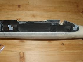 |
Bed Heads feature a Teflon sleeve which centers the pillar around the guard screw during application
and hardening of the epoxy.
Now is the time to remove these sleeves and leave a nice concentric
space between the guard screws and the pillars. No more filing one side of an off center pillar, for guard screw clearance.
| Picture #24 |  |
This is the completed bedding job. You can see the light colored surface in the bottom of the recoil
lug area. Even though we placed a layer of tape on the bottom of the recoil lug, I used a narrow chisel to scrape this
entire bottom surface to be certain that there are no obstructions that prevent the recoil lug from fully entering this mortise.
I leave all four sides of the recoil lug tightly bedded (no tape).
Remember that with a round receiver, the largest surface available to resist rotation is the side of this lug.
M-700 ADL PILLAR INSTALLATION (Installing M-700 BDL pillars, in an M-700 ADL stock)
The
M-700 ADL stock can be drilled for pillars without using the 2 ADL bushings included in your Pillar Installation tool Kit.
These bushings are only necessary when installing pillars in an M-700 BDL stock. Drill your ADL stock for
the rear pillar while the barreled action is being held on center in the stock by the front guard screw, as it passes through
the original ADL bushing. Pilot your pillar align cutter, on a Forster inletting guide screw to drill this
hole. After the rear guard screw hole has been drilled, remove the front guard screw, and the barreled
action from the stock. Now, use a drift punch and carefully tap the ADL bushing out of the stock.
Place your barreled action back in the stock and drop the rear BDL pillar, with its Teflon sleeve, into your stocks
freshly drilled ½" rear guard screw hole. Next, place your ADL trigger guard into it’s inletting in the
stock. Now install the rear trigger guard screw. This will, once again, center the barreled
action in the stock, while it is being drilled for the front pillar. Install a Forster inletting guide
screw in the receiver’s front action screw hole. Use your pillar align cutter to enlarge the front
guard screw hole to ½". Next, remove the rear guard screw, the trigger guard, the rear pillar with its Teflon
sleeve, and the barreled action from the stock. The next step will be to re-drill both of your ½”
pillar holes to 17/32nd.. You will not need to use any type of guide or fixture when doing this,
as the 17/32 drill will center itself in the smaller ½” holes. There are two reasons for enlarging
these holes. Just as when bedding a BDL rifle, your ADL bedding job will be completed in 2 steps.
During the first step, the pillars will be expoxied into the stock while they are attached to the receiver, by the
trigger guard screws. The larger 17/32” holes will allow the ½” pillars to drop freely
into the stock without placing unnecessary pressure on the receiver. These larger holes will also provide
a small amount of space for epoxy between the pillar and the stock. The hole for your front pillar will
have two diameters. The new portion of this hole will be 17/32”. The remaining
original portion of this hole is of course, sized to accept the ADL bushing which is .640" in diameter. This
leaves a “step” or a shoulder .054" wide where the 2 diameters join. Now is the time to
cut the BDL front pillar to a length that, when installed, will extend about .010" above this shoulder.
Extending the pillar slightly above this shoulder will allow hard contact between the lower end of the pillar
and the under side of the ADL bushing. Epoxy the pillars in place, in the stock, while holding the
barreled action and the stock together with rubber surgical tubing, as described in pictures #16 through #21 in the BDL portion
of this guide. The remainder of this bedding job will be completed in basically the same way as described
for the BDL. One exception is the need to re-install the ADL bushing. This bushing is not re-installed
until after the epoxy holding the pillars in place has hardened. Prepare for your 2nd application
of epoxy as shown in pictures # 22 through #24 above. After spreading enough epoxy to fill the space you
have just created between the stock and the receiver, you will pull the receiver down into this fresh bed of soft epoxy by
installing the front and rear guard screws. Tighten these only to about 10 inch lbs. DoNot install
the small diameter front trigger guard screw at this time. Doing so, will bend the receiver downward between
the 2 pillars that are providing the receivers only support until your 2nd application of epoxy has hardened. Whatever
steps I have skipped over in this description for the ADL, I believe you will be able to fill in the blanks by re-reading
the appropriate portions of the BDL instructions.
How
to check your work!
(or anyone else's for that matter)
| Picture #25 |  |
Many gunsmiths and target shooters talk about how a stress free receiver is a good thing. Receiver stress
is exactly what we are measuring here, and I know of no more accurate way to do it.
It will be of interest to both you and your customer to acquire a stress number from both before you start work, and
after your pillar bedding job is complete.
It was easier for me
to take a picture of this setup while the rifle was laying down in the horizontal position, ( this way I could hold the rifle
at camera height), but you will conduct the receiver stress test, and take both indicator readings while the barrel
is pointing straight up. By the way, one layer of tape on the magnetic base will prevent the barrel from being marked.
Now, with the barrel pointing straight up, and both trigger guard screws tightened to 30 to 35 in. lbs.,
zero the indicator while it is set up as shown in picture #25. Next loosen the front guard screw, and check the
indicator, how many thousandth's did it move? Make a note of this new reading, and re-tighten the front guard screw,
repeat this sequence a few times or, until you are comfortable that you have an accurate reading. Now repeat this
process with the rear guard screw. I have seen many rifles where the indicator moves from .025" to .100",
and a few even more.
After following these "Two Step" bedding instructions,The
most common numbers that I see, and numbers that I believe represent a good job, are .001 to .002 on the front screw, and
from .000 to .001 on the rear screw.
Remember Ernie's Rule:
For the least amount of stress in your action.
Build your actions foundation
while using the least amount of force!
No
liability is expressed or implied for damage or injury which may result from the improper installation or use of this product.
(Instructions above are for information only, do not add
to cart)
Item #2005
|

|