GUNSMITHING ODDS AND ENDS:#4 - ENSURE ALIGNMENT OF ALUMINUM BEDDING PILLARS
The "Pillar Align" kit in use.
Fastest setup, with the most accurate results.
Best of all, no expensive jigs, fixtures, or milling machines are necessary.
The following 12 Photos show how.
In a stock of wood or fiberglass you must build a solid foundation. With these tools, and the "Bed Heads" Installation process, you can also achieve an accurate foundation.
In order that your rifle sits squarely on the drill press table, attach a pair of weaver scope mount bases to the receiver. Be certain that the depth stop in your countersink is adjusted and locked in a position which prevents contact between the countersink and the receiver. See Picture #3
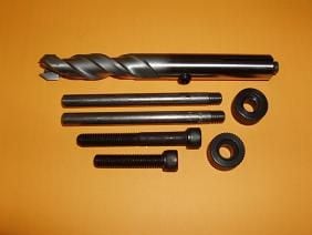
PICTURE #1
Use these tools to ensure alignment of pillars before they become captured in epoxy.No expensive milling machine, jigs, or fixtures are necessary for accurate location of aluminum pillars in your stock.
The "Pillar Align" countersink is piloted on the inexspensive, and readily avaliable Forstner inletting guide screw.
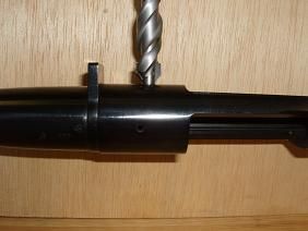
PICTURE #2
Here, we see a pair of Forstner inletting guide screws installed in a Remington M-700 receiver.The "Pillar Align" countersink has been placed down over one of these guide screws to illustrate how they work together.
PICTURE #3
The "Pillar Align" countersink has an adjustable stop.
Adjust this stop to provide about 1/8" to 1/4" clearance between the cutter and the receiver.
You should not drill the hole all the way through at this time.
PICTURE #4
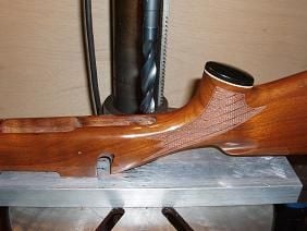
The factories have discovered the easy way to avoid guard screw alignment problems. Just make the hole bigger!
The guard screw hole in this stock is 3/8" in diameter and .050" off-center.The 2 drill bits are just my feeble attempt to help illustrate how far off center the factory trigger guard screw hole is.
PICTURE #5
The "Pillar Align" countersink will not be deflected by an off-center guard screw hole in the stock, because it is piloted by this guide.
A piloted Forstner bit does a good job of following the original hole (provided that you have the correct sized pilot). But when the original hole is off-center, the new hole for your pillar will also be off-center.
PICTURE #6
First: Center the barrel in the forearm by adding tape to the barrel,
as shown in Gunsmithing Odds and Ends #5, Picture #10.Second: Center the receiver in its inletting, by dropping an ADL bushing down over the rear guide screw, until it bottoms in the stock's trigger guard inletting.This is the way we center both ends of the barrelled action in the stock.
PICTURE #7
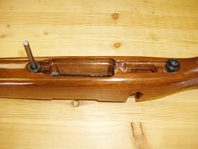
Next, place the other ADL bushing into the trigger guard inletting, and align with the hole for the front guard screw.
Now install and tighten the short allen head cap screw furnished in the kit.
This will hold the receiver centered in the stock after the rear ADL bushing is removed, and while the hole for the rear pillar is drilled.
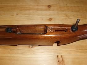
PICTURE #8
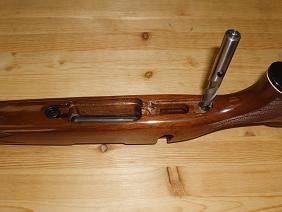
Here is the setup ready to be moved to the drill press and drilled for the rear pillar.After drilling, simply reverse the setup to drill for the front pillar, as shown in Picture #9.
PICTURE #9
Once again, center the receiver in the stock by dropping the ADL bushing down over the front guide screw, until it bottoms in the stock's trigger guard inletting.
Next, place the other ADL bushing into the trigger guard inletting, and directly over the ½" hole that you just drilled.
Now, install and tighten the long allen head cap screw before you remove the front ADL bushing.
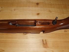
PICTURE #10
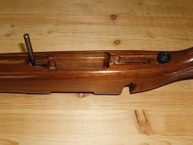
In this photo, the rear screw is tight, and the front ADL bushing has been removed.
This leaves the front guide ready to accept the " Pillar Align" countersink.
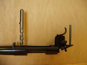
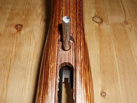
PICTURE #11
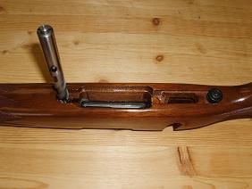
Here, the "Pillar Align" countersink has been placed over the front guide screw which makes this setup ready for the drill press, and drilling the front pillar.
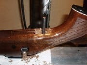
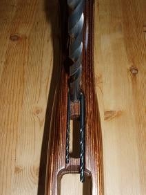
PICTURE #12
Now it is time to complete the final 1/8" to 1/4" that remains undrilled.
The main concern is to complete these holes in a way that is least likely to chip the stock as the cutter breaks through the surface on the other side.
If the stock were chipped while completing the rear guard screw hole, this chip could show in the area of the rear receiver tang.
I have never had a problem when completing these holes with a sharp 17/32" drill bit, as shown in Picture #12.
This drill bit will center itself in the smaller 1/2" hole and no guide will be necessary.
Remember Ernie's Rule:For the least amount of stress in your action, build your action's foundation while using the least amount of force!